There are three major types of lenses used in lighthouse towers – fixed, flashing, and a combination of fixed and flashing. Flashing lights are the most effective and powerful. The first lens created by Augustin Fresnel was a flashing lens. The flashing lens rotates and has a number of bull’s-eye lens panels that create beams of concentrated light (an eight-panel lens produces eight beams). As the lens rotates, the beams successively pass the view of the mariner giving what appears as a flash of light followed by darkness. Beneath the flashing Fresnel lens are several unusual mechanisms used to rotate and control the lens. The lens will be found to be supported on wheels, ball bearings, or on mercury contained in a large metal tub.
During 1822, Augustin Fresnel worked on completing his design for a flashing lens using eight of his circular bull’s-eye flash panels. Each of the bull’s-eye panels refracted (deflected) the light in both the horizontal and vertical directions, forming beams of light. The light from each bull’s-eye lens panel, lit with a four-concentric-wick lamp, was determined to be equal to three and one-quarter of the best 31-inch reflectors then in use. In addition to the bull’s-eye flash panels, he added eight small trapezoidal lens panels, placed at a 25-degree angle, above and behind the bull’s-eye flash panels. These lenses collected the light above the burner and directed it onto eight large flat mirrors placed at an angle to reflect the light horizontally above the main bull’s-eye panels. The trapezoidal lenses and upper mirrors were designed to collect the approximately one-fourth of the light from above the lamp burner and to increase the duration of the flash, as seen by the mariner, by about double that of the flash from the main lens panels alone. He also added four rings of small mirrors below the main bull’s-eye panels, to collect light below the burner and direct it horizontally to the near vicinity of the lighthouse. The mariner would see a long dark period followed by a brilliant flash of light and another dark period, etc., as the lens revolved on its axis.
Revolving lights produce flashes that occur at regular intervals. When flashing lenses were first invented, friction caused by their great weight, plus the weak power of their clockwork-driven rotation machinery delivered extremely slow rotation speeds of about one revolution in eight minutes. This caused the length of the flash to be quite long, 20 seconds or more, and the interval between flashes to be extremely long, at nearly one minute. The first attempts to shorten the flash time were accomplished by increasing the number of bull’s-eye flash panels used in the lens and also by increasing the speed of rotation. It was generally thought that the shorter the duration of the flash, the better it would be for the mariner. With 24-panel lenses and large clockworks, it became possible to produce flashes with a duration of as little as five seconds, and an interval of 15 seconds between flashes. Later, when the mercury basin was invented, it became possible to significantly increase the speed of lens rotation. Flashes of three-tenths of a second, and intervals of 10 seconds between flashes became common. The French took this to its maximum capability and produced a flash duration of as little as one-tenth of a second in their ‘feux-éclair’ or lightning lens. However, this was too fast for use under all weather conditions and mariners complained bitterly. Eventually, a de-facto standard was established at a minimum of three-tenths of a second for flash duration.
Three types of apparatus were employed to allow the rotation of a lens:
When Augustin Fresnel created his first revolving lens it was mounted on small (about 5 inch or 12cm. diameter) wheels. These wheels acted as roller bearings to support the weight of the lens and to allow it to rotate freely. Fresnel described the rollers in his first paper in 1822 as:
“This apparatus can easily be turned around its axis on the column by means of rollers, which move upon a circular projection on top of the pedestal.”
When his lenses were first used in Scotland, England, and America this roller assembly was renamed the chariot, and the rollers, chariot wheels.
A steel ring or plate attached to the base plate of the lens rested directly on these wheels, which ran on a steel track on the top of the lens pedestal. In addition, there were guide rollers rotating horizontally that were in contact with the central pivot shaft to prevent any lateral motion of the lens assembly. Chariot wheels were first made of bronze and, later, of hardened steel. The chariot wheel system worked well for lenses that were turned at slow speeds, but when rotation was greater than about one revolution per two minutes, too much friction was created. This was especially true if the lens was larger than 3rd order. In addition, the chariot wheels were expensive to manufacture and both the wheels and the track they rode upon deteriorated within a few years and had to be replaced. Chance Brothers in England tried to correct the problem by designing a tapered chariot wheel. Unfortunately, this was only a relatively minor improvement.
David Heap, the American engineer assigned to the Third District Depot, decided to look for a less costly rotation method that would still meet the needs for rapid revolution of the lens. Heap first tried ball bearings during 1893, but did not use the ball bearings throughout the rotation assembly, and while rotation speed was improved, friction was still evident and this arrangement was not put into general use.
In 1895, Trinity House, the lighthouse authority of England, built a giant ball bearing assembly six feet in diameter with balls that were two inches in diameter for use in a 1st order lens. However, this bearing produced too much friction and was abandoned.
In 1898, Heap redesigned the lens support pedestal and the clock used to revolve the lens. Thrust and guide ball bearings were substituted throughout the lens support to replace the chariot wheels in lenses of the 3rd, 4th, and 5th order. He was able to create a vastly improved design for the smaller lenses. The new 4th order ball bearing lens was first installed at the Romer Shoal light in New York. Rotation speed increased to one revolution every 20 seconds. The ball bearings and race plates were made of the best tool steel, hardened, tempered, and polished. The balls were kept lubricated and under a cover to keep them free of dust and dirt, and were easy to maintain and replace as the need arose. A 3rd order ball-bearing lens was first installed at the Sturgeon Bay Ship Canal light in Wisconsin in 1899.
In a letter written on April 19, 1825, Augustin Fresnel proposed the use of mercury to reduce the friction in revolving lenses. His statement follows:
“I propose to float our rotating devices, of the first order, in a bath of mercury, instead of placing them on rollers. This project won't present many difficulties; nevertheless, as I have not put it into execution, I won't require you to adopt it for your first lighthouse.”
Fresnel’s plan for mercury flotation was not put into practice until 1890 when Monsieur Leon Bourdelles, Chief Engineer of the French Lighthouse Service, designed and built a workable mercury flotation system. The mercury bath allowed the lens to operate in an almost frictionless environment and, additionally, allowed the speed of rotation to be dramatically increased.
Mercury float with section removed, showing the float attached to the bottom of the lens and basin attached to the pedestal.
The mercury bath was experimented with at the La Teignouse Lighthouse in France during 1892 and was first installed at Cape La Heve, France in 1893. Mercury flotation was first used in Scotland in 1898. Later, Dr. John Hopkinson of Chance Brothers in England did further work to improve the mercury float design.
High-speed rotation could not have been accomplished without the use of the mercury bath system, unless the driving clockwork was significantly increased in its power output, which would have been nearly impossible. The mercury bath consisted of a donut shaped basin in which a relatively small amount of mercury was placed. Attached to the base of the lens was a large donut shaped ring that was submerged in, and supported by, the mercury, which was placed in the basin. This assembly provided a nearly friction less base for the lens to ride upon, allowing lenses weighing several tons to be started in motion with the push of a single finger. Mercury basins also had ball or roller bearings set in a track around the top of the central pivot shaft that kept the ring, attached to the lens, centered within the basin. When the lens rotation was speeded by use of the mercury floatation system, lens panels could be reduced in number and increased in size, giving a much brighter flash.
First Lens with Mercury Bath Cape La Heve, France (1893).
The use of mercury as a replacement for chariot wheels or ball bearings posed a problem for the keepers who had to work with the liquid mercury. There was as much as 500 pounds of mercury in the basin of a 1st order lens. Mercury poisoning can easily occur from the mercury itself or from the vapor, which is always present around the basin. Mercury can be absorbed through the skin or the vapor can be breathed in through the lungs. In either case, mercury poisoning will cause permanent damage that is very difficult to diagnose. Often, mercury poisoning will cause severe mental problems. The keepers were required to keep the surface of the mercury clean and to ensure the mercury was maintained at the proper level by adding or removing the liquid mercury as needed. This brought the keepers into periodic contact with the mercury and its fumes. A common practice, used to reduce the amount of fumes from the mercury, was to pour a layer of ordinary motor oil onto the surface of the mercury in the basin.
Early use of the mercury flotation system in the United States
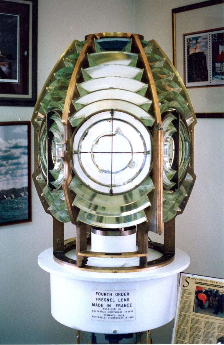
A mercury float, including pedestal and clockwork case, was built and tested at the general lighthouse depot in Tompkinsville, New York for use in the Ashtabula Harbor Light Station, Ohio. This was the first mercury float built in America and was installed in 1915. It was designed along lines similar to those then in use for large lenses, and was intended for the smaller sizes of illuminating apparatus. A test run showed that when no mercury was used, 200 pounds was the least weight that would start the lens in motion. By using mercury, the corresponding weight required was 75 pounds, the revolving portion of the apparatus weighing 400 pounds, with 10.5 pounds of mercury in the basin. Added weight on the float made no difference in speed, and when too much mercury was used the speed was only slightly increased. Doubling the driving weight increased the speed very slightly with full operation of the governor.
The Ashtabula Lens on its Mercury Pedestal.
A 6000 pound mercury float and pedestal, the largest constructed in this country, was successfully installed at Cape Fear Light Station on May 22, 1920, replacing the worn-out 1st order lens chariot, which had been in constant service since the completion of the station in 1903.
The Cape Fear lens was an old 1st order apparatus with an inside diameter of 6 feet 1 inch composed of 24 flash panels. The combined weight of the lens, platen, and mercury float was in excess of 6000 pounds. It was revolved at the rate of one revolution in four minutes by a type D 1st order clock. The lens platen, or table, was 6 feet 2 inches in diameter and rested on a cast-iron circular float, 4.5 feet outside diameter, 3 feet inside diameter, and 13 inches deep. This float revolved within a cast-iron basin containing the mercury, with a clearance of one-sixteenth inch around the sides and bottom. The lens was maintained in a vertical position by a tool-steel track secured to the underside of the lens platen, bearing on six conical hardened steel rollers and mounted on ball bearings. It was centered by six guide rollers that bear on the outer periphery of the same track. The basin was supported on a casting provided with four leveling wedges. Four cast-iron columns about 7 feet long, resting on a cast-iron base, supported the casting. The lens was revolved by means of a 36-inch bronze internal gear fixed to the lens platen, driven by a 6-inch spur gear connected to the clock by a long, vertical drive shaft provided with universal joints.
One of the earliest mercury floats installed in America was at the Cape Charles Lighthouse in 1895.
1st Order Cape Charles - Mercury Float in base behind Clockwork.
poop_ship on February 18th, 2021 at 19:13 UTC »
Makes me wonder about the real driving force behind of lighthouse keepers going mad from the isolation. Rather than isolation, mercury poisoning.
HockeyCannon on February 18th, 2021 at 17:34 UTC »
The outside screen of the old projection TV's of the late 80's is a fresnal lens. People make solar "death rays" out of them.
https://www.instructables.com/Giant-Fresnel-Lens-Deathray-An-Experiment-in-Opti/
https://www.youtube.com/watch?v=OmlXR2nsis4
H_Lunulata on February 18th, 2021 at 17:26 UTC »
The lighthouse at the Canada Science and Technology Museum, formerly the Cape North lighthouse, is built that way, with a giant class fresnel lens floating in a giant vat of mercury.
Made a real toxic mess when we had a magnitude 5+ earthquake here in 2010.